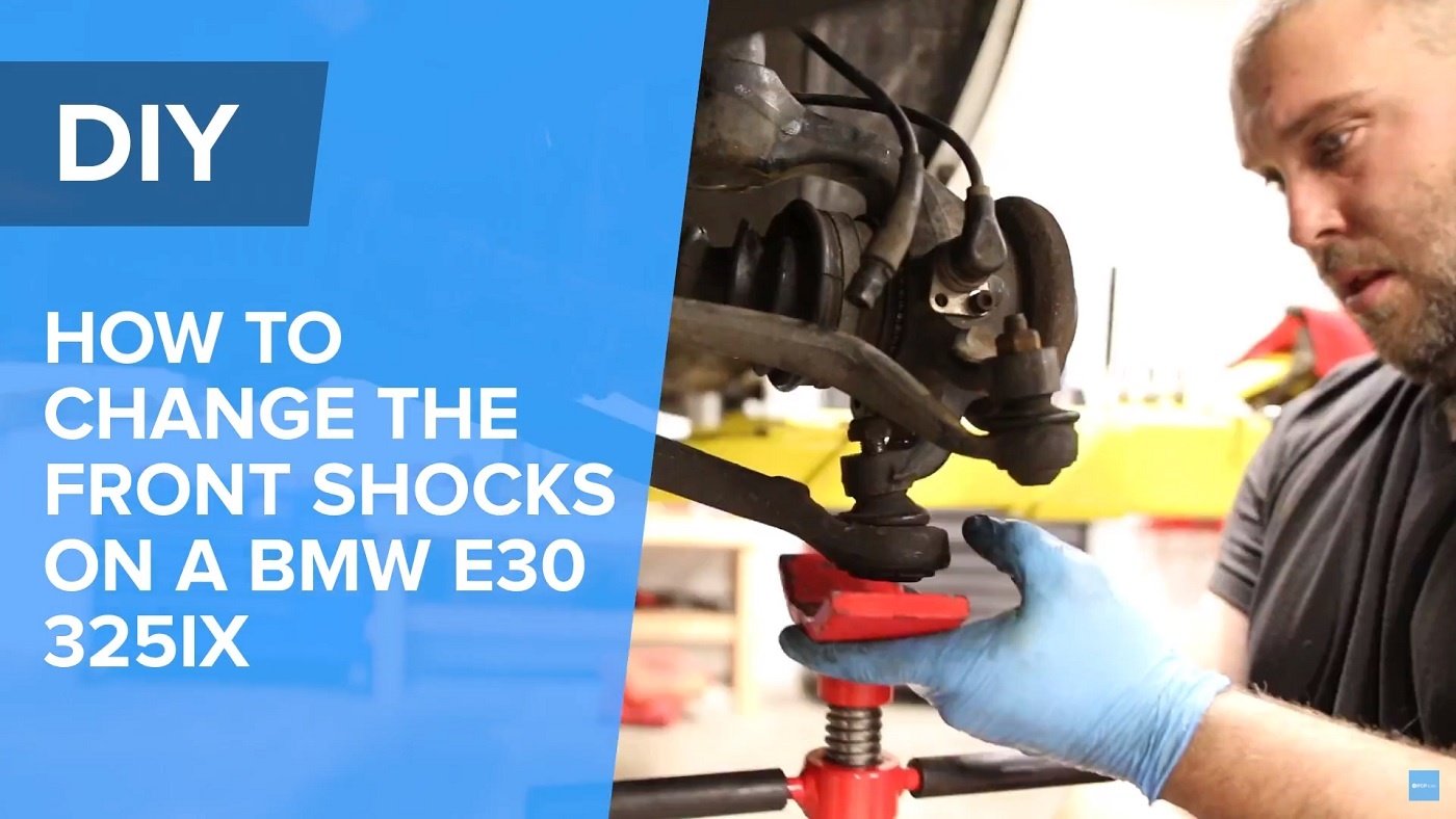
Does your E30's front end feel sketchy over bumps? Here's how to fix it.
Bad shocks often create an uncomfortable ride that becomes sketchy on uneven or bumpy road surfaces. Shocks help dampen the springs, and a worn shock absorber means the time your tire spends in contact with the road is minimized, when it should be maximized. This issue affects all vehicles of all ages and is not just an old car problem.
In this repair, we are replacing shock inserts on an E30 325ix. The repair procedure is pretty much the same on all BMW E30's except for dealing with the front axle. On a regular rear-wheel drive E30, you can technically replace the insert with the housing on the vehicle but I find it easier to remove the entire assembly and work on a bench with a vice. We also decided to install Bilstein B6 Performance shock inserts in this DIY to improve handling performance and response. Afterall, Bilstein yellow body shocks + E30 is a winning formula.
Tools needed to complete the repair:
- 10mm socket/wrench
- 13mm socket/wrench
- 17mm socket/wrench
- 19mm socket
- 22mm wrench
- 30mm socket (xi models only)
- Ratchets
- Breaker bar
- Punches/chisels
- Hammer
- Scissor style ball joint tool
- Spring compressor
- Torque wrench
- Strut insert (your choice based on what you're looking to achieve)
- Strut mounts
- Bump stops (included with Bilstein HD strut)
- Dust bellows (included with Bilstein HD strut)
- Strut mount nuts (included with Bilstein HD strut)
Video: For a full tutorial on the process, click the video below and don't forget to subscribe.
Step 1:
Get the vehicle properly supported in the air. Always make sure the vehicle is stable before putting any part of your body under the vehicle. If on jack stands, throw the wheels under the car as a safety and if you're fortunate enough to work on a lift make sure the lift is sitting on the locks.
Step 2:
To do any inserts, I prefer to remove the entire assembly from the vehicle. I find it easier to disassemble and reassemble off the vehicle, on a bench. First, remove the brake caliper and caliper carrier using a 13mm socket/wrench and and 19mm socket/wrench. I also remove the brake rotor to reduce any possible weight. Usually there is a set screw securing the rotor to the wheel hub and that is secured with a 5mm hex screw. Optionally, remove the dust shield if you're concerned with it getting bent. The dust shield is held on with three 10mm bolts.
Step 3:
Remove the ABS wheel speed sensor from the knuckle with a 5mm hex socket. These sensors have a tendency to get stuck in the bore so it helps to have some lubrication available. I also tap the sensor loose by hitting the metal flange gently using a punch until the sensor begins to move side to side. Once it's moving you can remove it fairly easily.
Step 4:
Now you'll remove the tie rod locking nut and control arm locking nut. Using a 17mm socket or wrench remove the tie rod end nut. The lock nut for the control arm is 22mm and you will need to use a wrench to gain access to it. Once the nuts are removed use a scissor style ball joint tool to safely pop the ball joints from the knuckle. The scissor style ball joint tool will prevent damage from occurring to the ball joint boots upon removal.
iX Models Only:
For iX models you will need to remove the axle from the front hub. Using a 30mm socket remove the axle nut. The axle nut is torqued in place really tight so an impact gun is recommended. If you don't have an impact gun you will need a breaker bar to gain the appropriate leverage to break the nut free. The axle can be stuck in place/stubborn to remove due to corrosion between the splines and CV joint. I use a punch and hammer to slowly break the axle free from the wheel hub. Once it starts moving you're in good shape. You will also need to remove the sway bar link. I find it easier to disconnect the sway bar link from the sway bar due to access. To do this you will need a 17mm socket/wrench. if the ball joint is spinning in the sway bar link use needle nose vice grips on the exposed metal portion between the sway bar and rubber boot to counter hold the joint. At this point you can remove the axle from the wheel hub. Make sure the inner joint doesn't move outward too much. Also secure off to the side to prevent the inner joint from falling apart.
Step 5:
Remove the three 13mm nuts on top of the strut tower while supporting the strut assembly below. Once the nuts are removed the entire assembly can be removed from the vehicle and worked on off to the side.
Step 6:
I used a shop vice to support the assembly. Using a spring compressor tool release spring tension between the lower and upper spring seat. To remove the strut mount I used a 19mm thin wall impact socket to remove the top nut. The size of this can vary based on which brand of strut insert is installed. The insert was junk so I used a vice grip to clamp onto the piston shaft to prevent it from spinning. Never do this if you plan to reuse the insert as it will scratch the machined surface which in turn will destroy the oil scraper seal of the shock causing leaks
Step 7:
Now it's time to remove the gland nut that secures the shock insert into the strut housing. The gland nut can be seized into place on these strut housings. It is possible that it's impossible to remove this nut altogether which would require to replace the strut housing as a unit. In my case, I was able to remove this gland nut using a punch and a hammer. With the gland nut free I was able to remove the strut insert. The Bilstein B6 Performance strut insert includes a new special gland nut which is sized differently than the stock sized one. Before dropping the new insert in I poured a little bit of ATF into the housing. This is used as a coolant of sorts for the strut insert.
Step 8:
Reassembling the strut is the reverse process of taking it apart. I recommend using a tiny bit of anti-seize on the threads of the gland nut to aid in removal in the future. Make sure the spring is oriented in the correct direction and that the ends of the coil spring are fully seated in the lower and upper spring seat. If you're replacing the strut bearing make sure it is greased properly. When tightening the top nut it's best to thread it on and use spring tension to keep the piston shaft from spinning (but only after this nut is fully engaged on the piston shaft). When installing the strut housing/assembly back on the vehicle make sure all suspension components are tightened with the suspension resting at ride height.
Key torque specs for reassembly:
- Strut Gland Nut (External Hex) - 65Nm
- Strut Gland Nut (Internal Hex) - 44Nm
- Strut mount nuts (to strut tower) - 22Nm
- Tie rod end nut - 37Nm
- Control arm to knuckle nut - 64Nm


