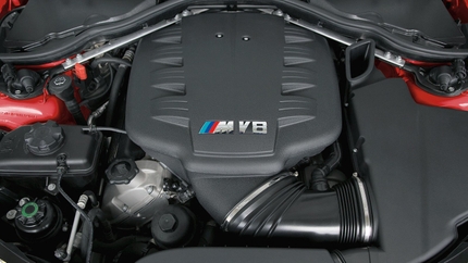
For those of you with a BMW N51/N52/N52T engine you will know that given the design of this motor, it means positioning the starter directly underneath the air intake manifold. Meaning that to replace a worn out starter you will have to remove the air intake tract and air intake manifold to access it. The labor required to do so and the money involved getting this serviced through a shop, or even worse a BMW dealership can be extensive.
In this article we will walk you through the process of replacing a worn out starter in our subject vehicle 2006 BMW 325Xi.
"We will take you through step by step to show you that though this is a tedious process you can in fact, get this job done yourself and save yourself some serious cash."
Though I’m the VWG Catalog Manager I’m also, it appears, our Office Manager Joe Coppola's personal mechanic/handyman (that is another story, let's just say I will not be helping him install the quarter round moldings in his new house after the debacle we had at his old one). So I wasn’t surprised that I got the call when he got back from vacation to find that his car would not start. Not one to miss an opportunity to help a friend I told him have it towed to our shop and l would take care of it for him.
With some help from Kyle Bascombe and a long time customer of ours Isaac, who stopped by to pick up some parts and decided to stick around and give us a hand, we managed to get this job done in just over three hours. Mind you we took our time and were not in a rush, so you may be able to get this done a bit sooner.
Here is what you need to get started
- Replacement Starter, rebuilt unit from Bosch was ordered
- Replacement Aluminum BMW Starter Bolts
- Replacement Air Intake Manifold Gasket Set From Victor Reinz
- Though not necessary a Replacement Throttle Body Gasket was also ordered up as well from Victor Reinz
- Assorted BMW tools, Torx Bit Sockets, E-Torx Sockets along with basic hand tools.
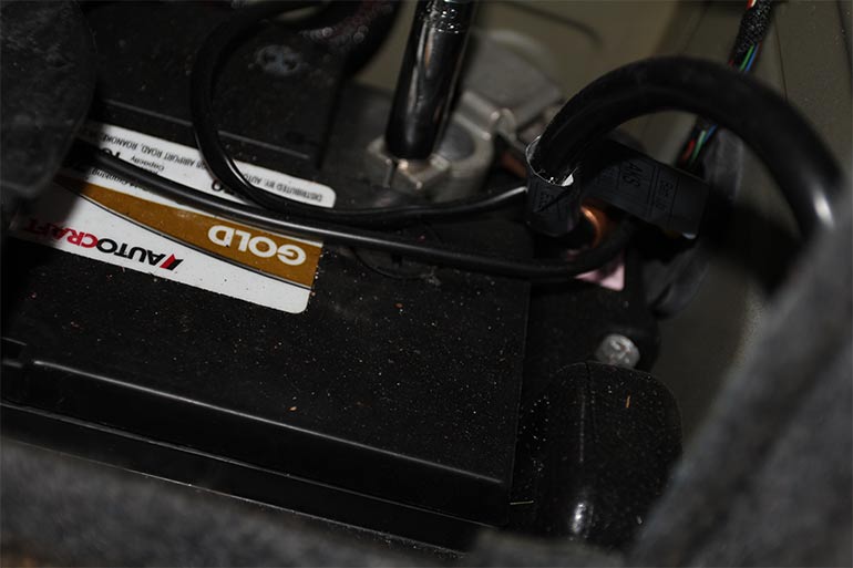
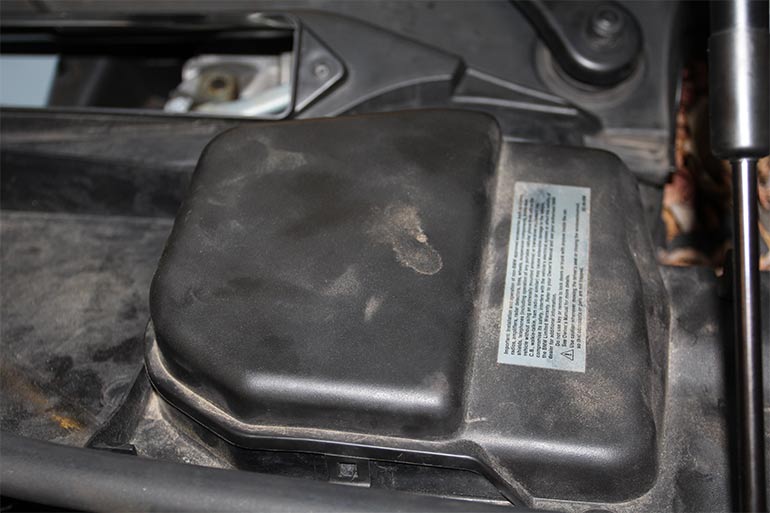
We begin by locating the battery in the trunk compartment underneath a storage panel on the passenger side and removing the negative cable with a 10mm extended socket, and secure the cable to the side.
We can then make our way to the front engine compartment and begin to make room for removal of the intake manifold by removing two side panels beside the compartment for the cabin filter. These just snap out of place, and have a small grooved grommet along the fender that hold a rubber trim against them.
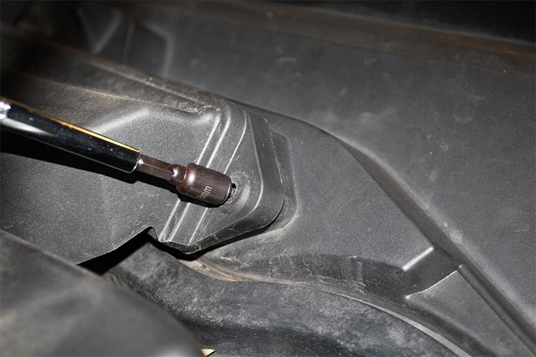
With these removed with that remove the 8mm retaining screws surrounding the housing for the cabin filter and remove the housing and cabin filter as a unit.
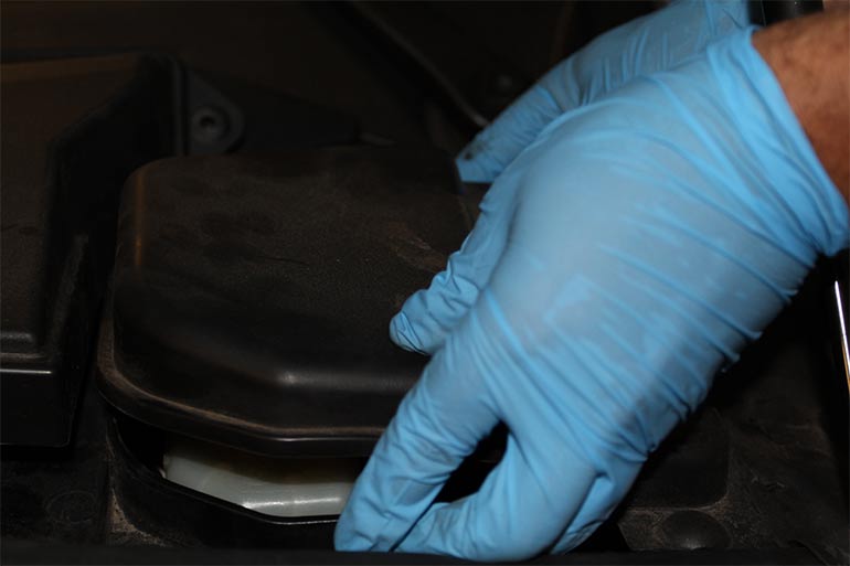
We can then start removing the cover for the engine harness and battery cable from this same cabin filter tray.
Remove the harness from underneath this cabin filter tray, being careful not to break the retaining clips attaching the holder (on our subject vehicle some of the tabs for the harness were already broken).
Then we can remove a sensor connector and set aside the harness on the passenger side of this cabin filter tray.
We can then remove the cabin filter tray itself.
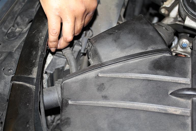
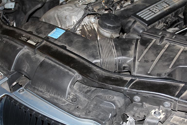
After these are removed you can then work your way to the air intake duct and intake box. You will need a T20 Torx socket to remove the retaining screws at the front of the duct over your radiator support.
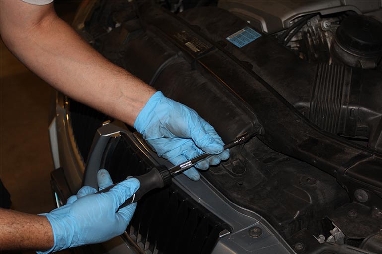
And using an awe or small flathead screwdriver pry on both side of the duct to remove it from the air intake box.
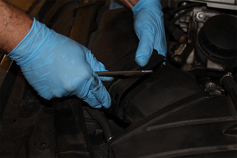
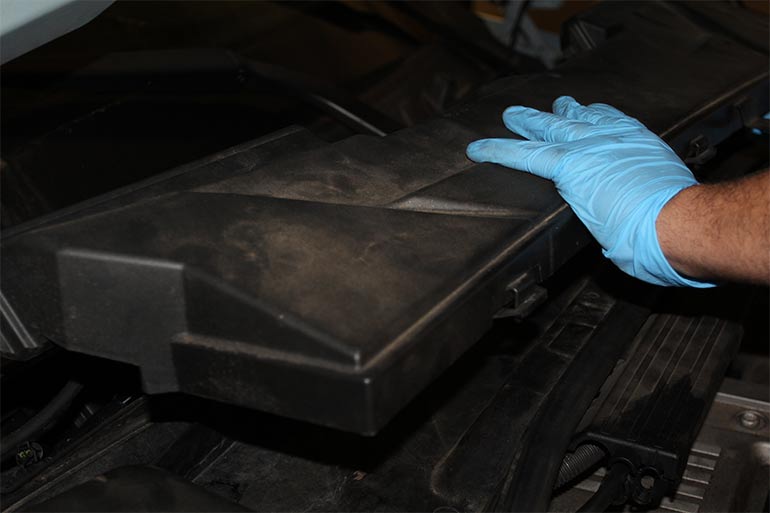
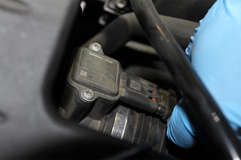
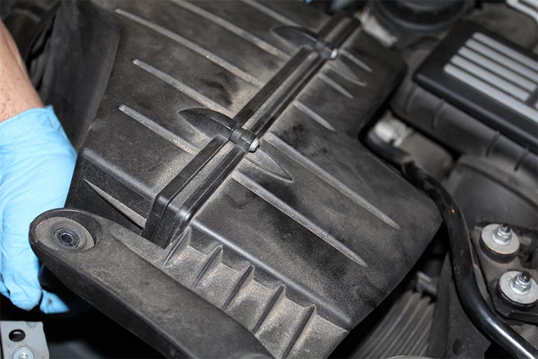
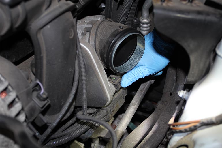
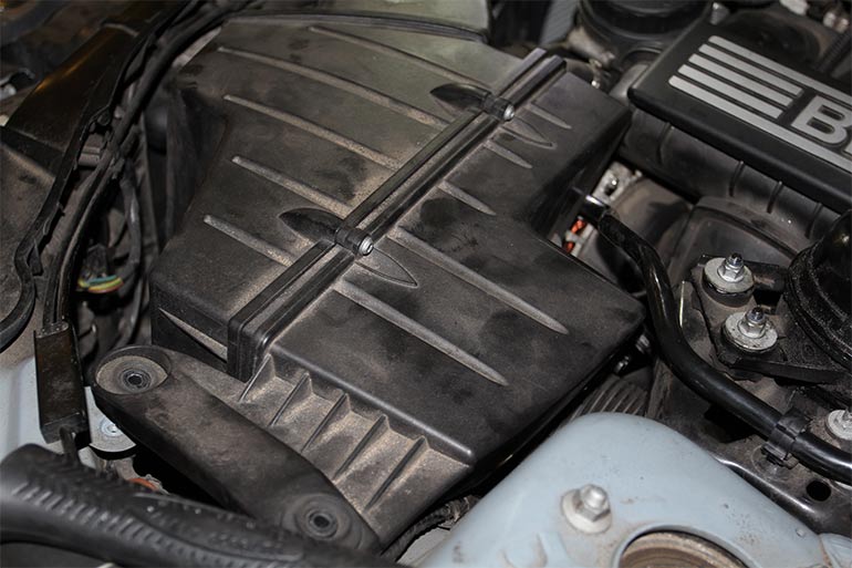
Now to move onto the box, start by removing the disconnecting the Air Mass meter connector from the sensor and setting it aside, then loosen the hose clamp at the box closest to the sensor.
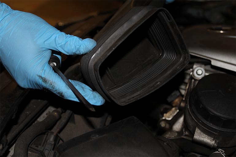
Now remove the two 10mm screws holding down the box to the frame, and work the box off the hose, and off of the rubber knob that retains it.
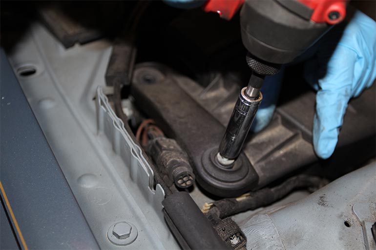
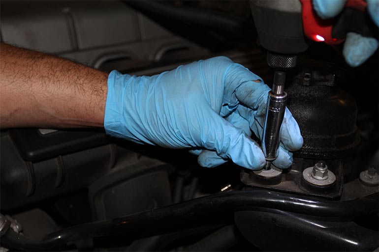
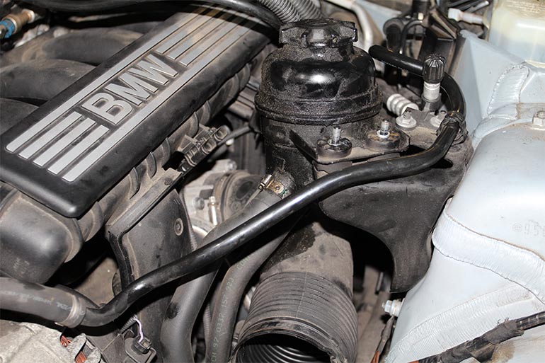
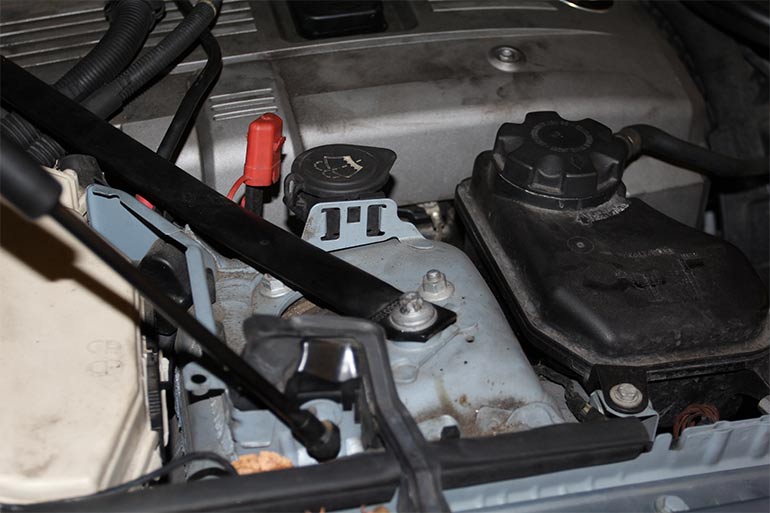
Now you can begin removing the power steering reservoir from the retaining bracket, by removing the two 10mm nuts and washers.
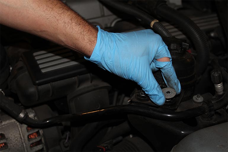
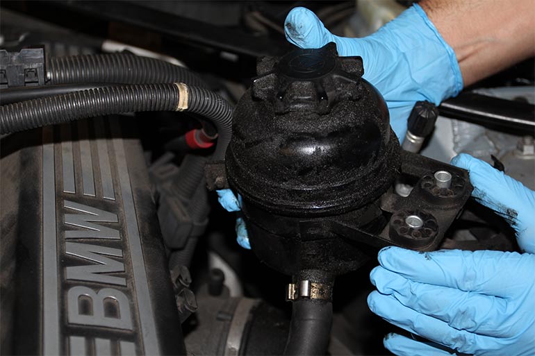
Then simply lift the power steering reservoir out of place and set it aside (you will not need to worry about disconnecting any hoses, and as long as your reservoir cap is nice and tight there is no concern for losing fluid).
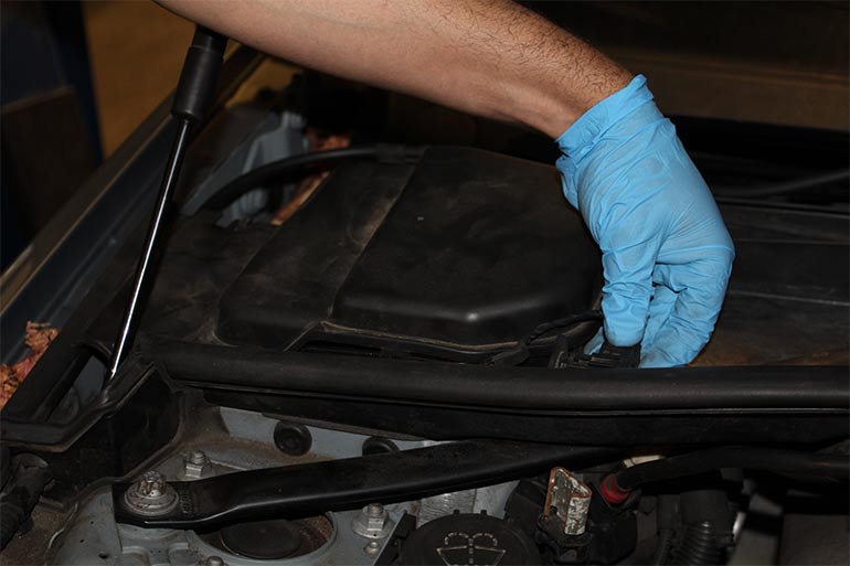
Now you can remove the connector for the booster vacuum hose located on a rear bracket near the firewall, the clip on this hose was a bit brittle and did not want to budge, so do not get discouraged if it takes you some time. Once removed you can also set it aside as you did the reservoir.
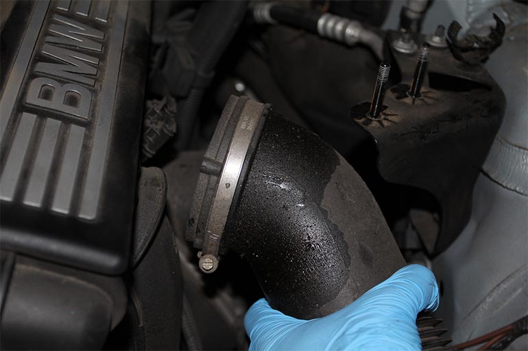
From here we can remove the remaining air intake hose leading from the throttle body elbow.
Now you can remove the electrical connection leading to the underside of the throttle body facing you.
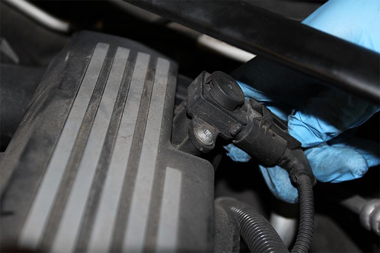
After that unhook the two harness connections from their metal retaining bracket and disconnect your MAP sensor connector from your sensor.
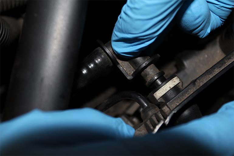
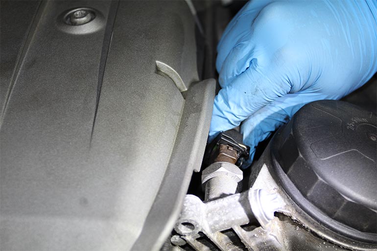
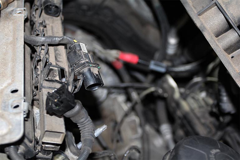
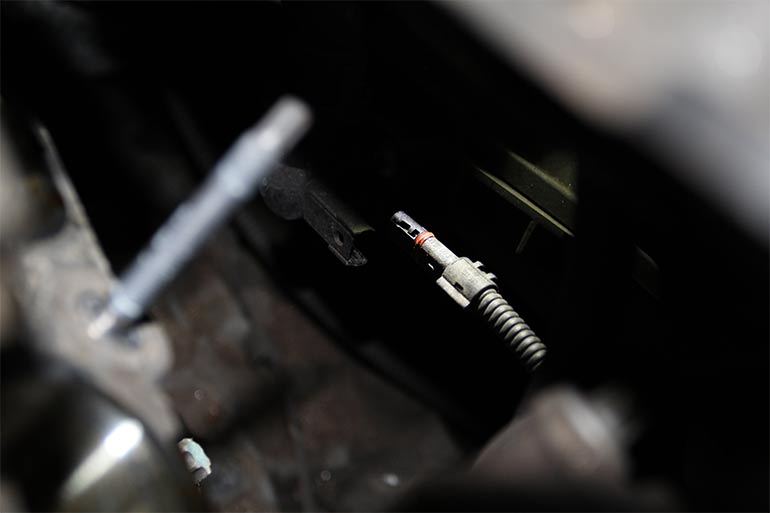
Back towards the front of the engine we disconnected the oil pressure sensor, these use a typical metal spring that you must depress in order to remove.
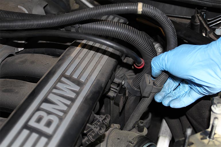
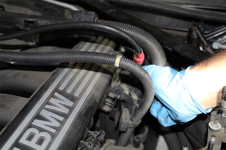
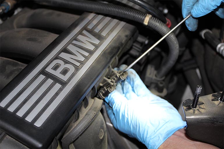
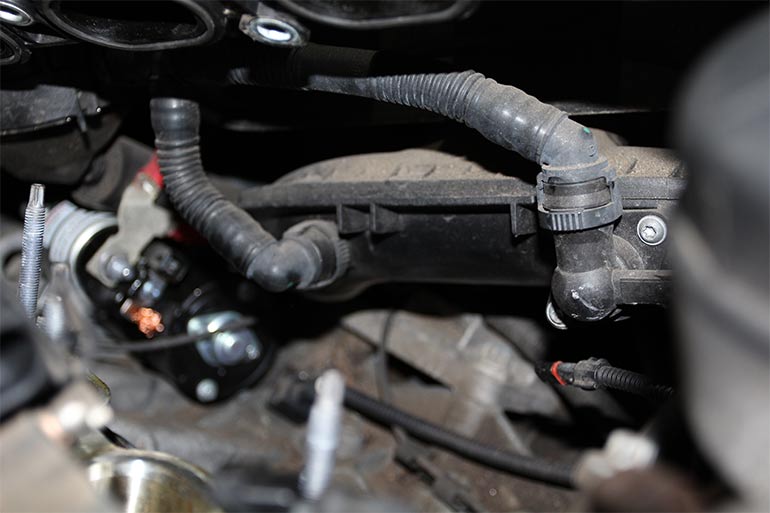
Then we began removing the fuel line retaining screw from retaining bracket at the rear of the intake manifold. Here you can also remove the breather hose that move along the back of the manifold, also by pressing on two tabs on either side of the connector.
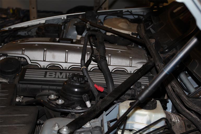
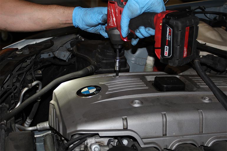
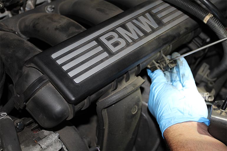
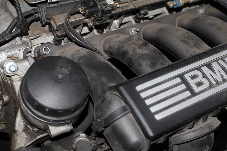
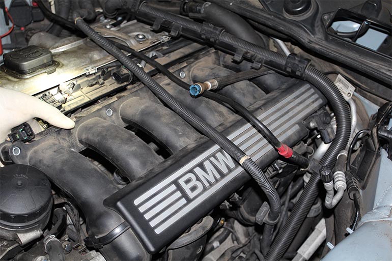
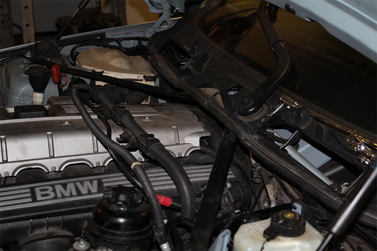
Then we went ahead and removed the engine plastic cover to get access to the intake manifold retaining bolts.
Back at the intake side of the engine we removed two small electrical connectors facing us, using a small awe to unclip them from the manifold.
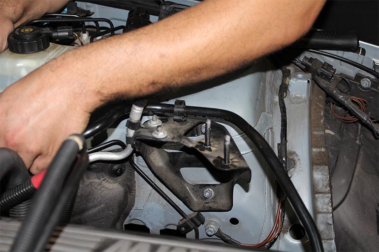
At this point though not necessary I went ahead and remove the bracket for the power steering reservoir as it helps give you much more room to work. Again you can skip this step, but I was in no rush, and like to have as much room as possible.
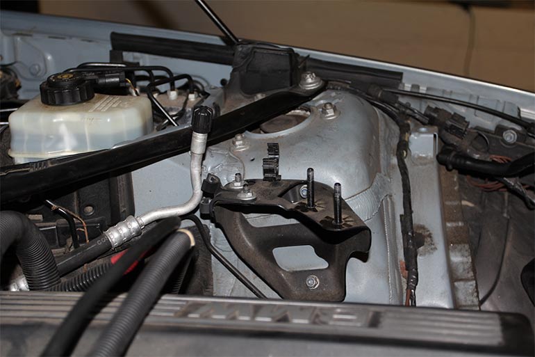
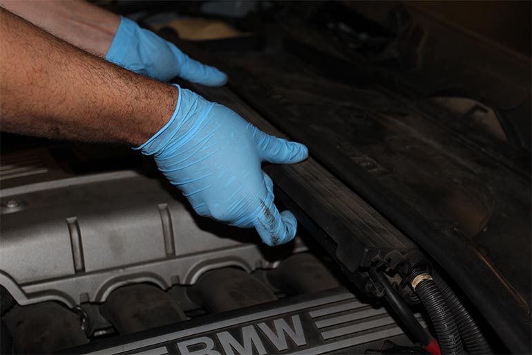
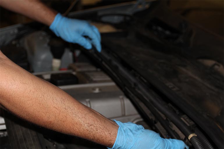
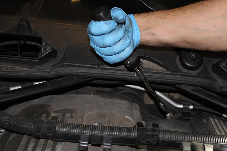
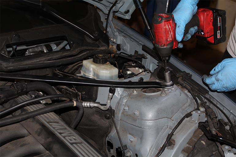
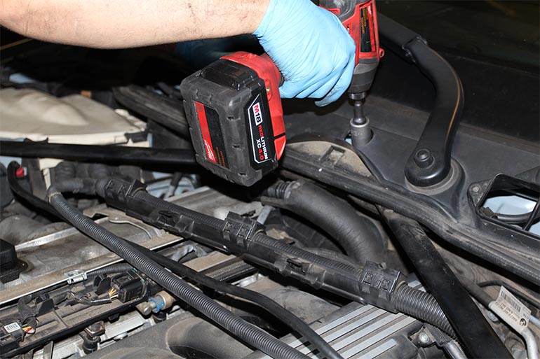
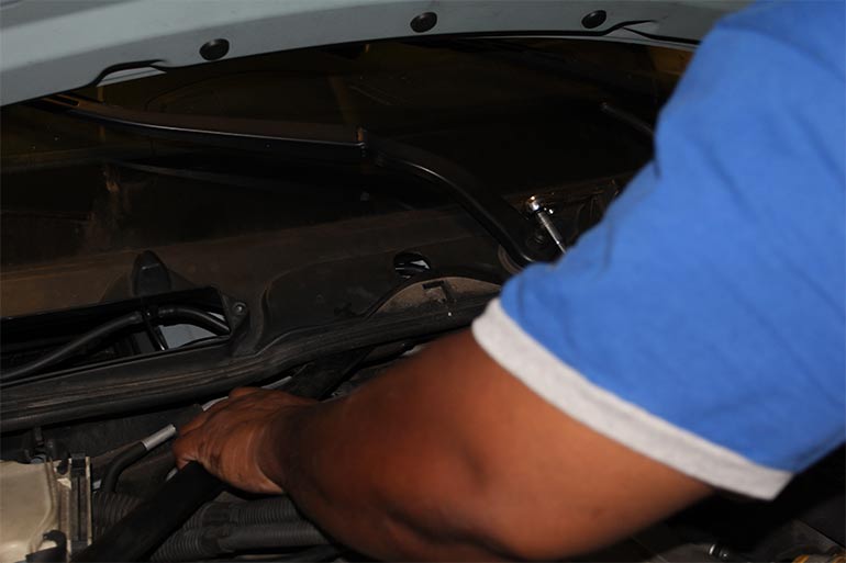
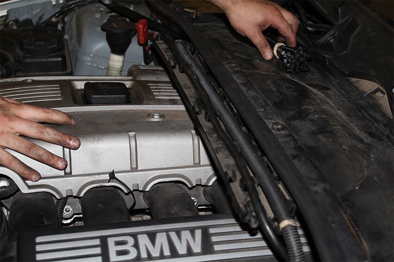
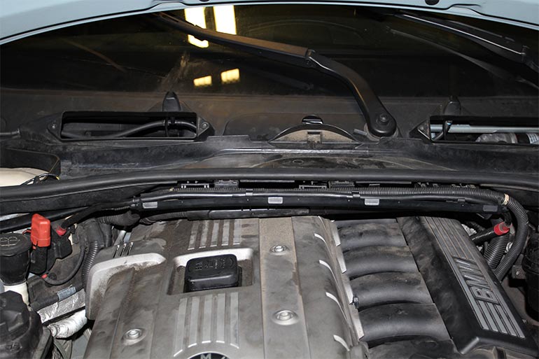
Now you will see a set of strut bars left and right leading from either strut tower to the center of the vehicle cowl. You then have to remove each bolt from each tower and loosen (but don’t remove) the center strut cowl.
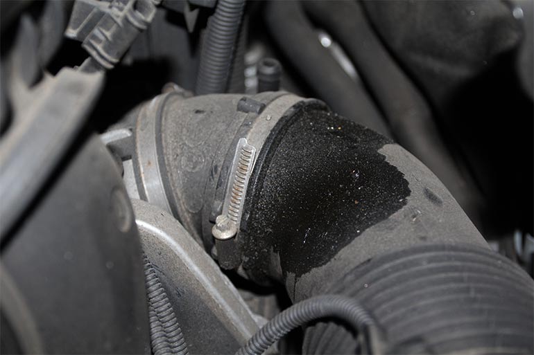
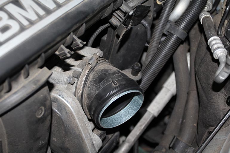
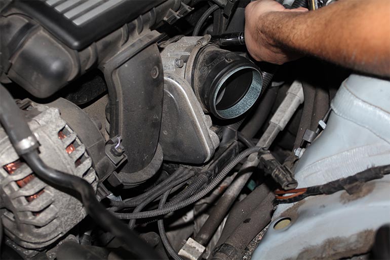
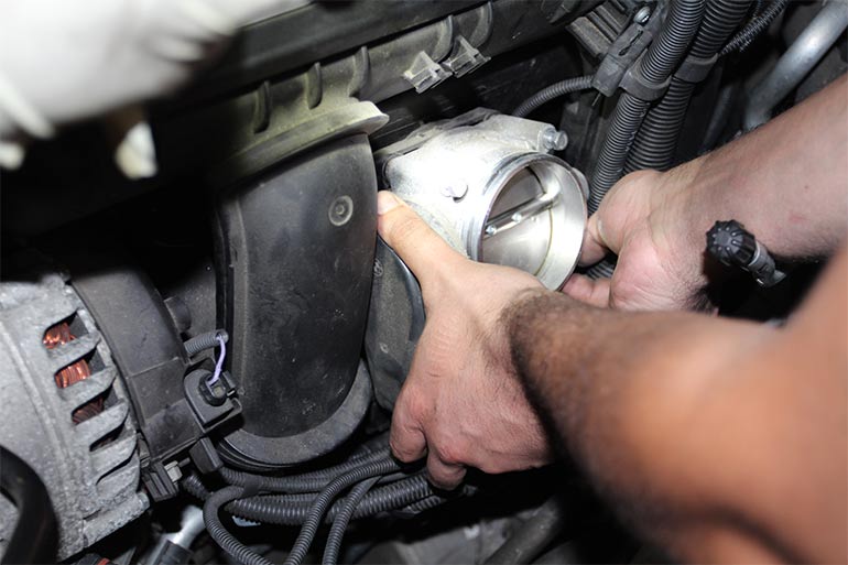
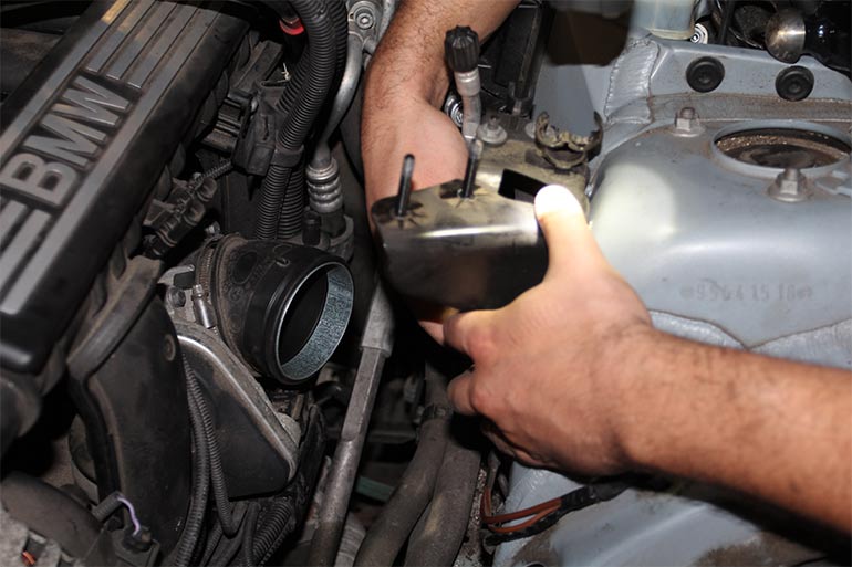
Now with a good view of your throttle body you can see a small intake elbow coming out of it. Use a flat head screw driver, or in our case a small 6mm socket to loosen the clamp on this hose and gently pry the hose off the throttle body.
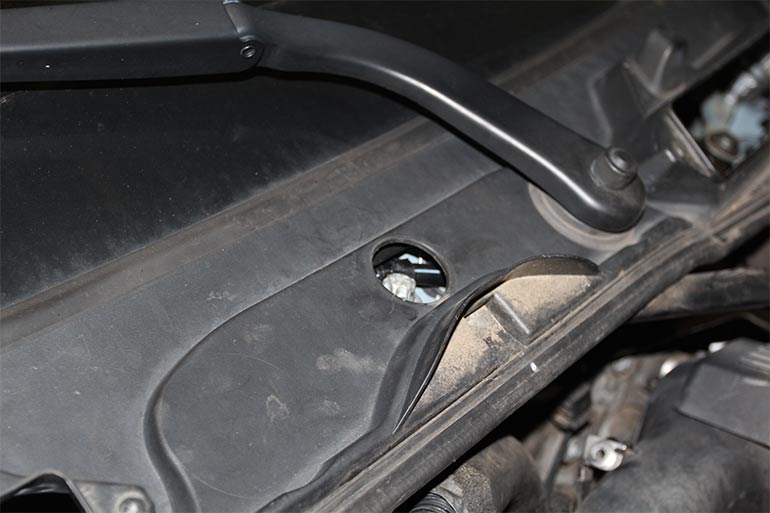
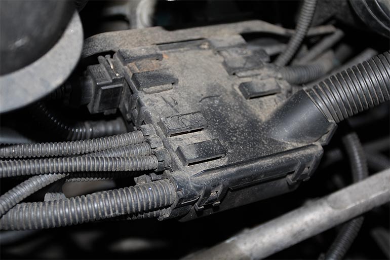
Now this next step is also not necessary but we did it any way. Underneath the throttle body there is what is called a junction box which is a small plastic box attached to a bracket under the throttle body. This box will need to be removed so you can remove the intake manifold as its retaining bracket is mounted to it and gets in the way. There are two metal tabs you are to reach in and unhook in order to remove the box, one is barely visible and the other would lays underneath the left side of the throttle body. Apparently there is some magic way to reach them and remove them, but I’m not one for witchcraft or wasting time so I simply unbolted the throttle body for a better view of the box.
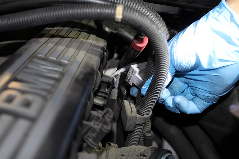
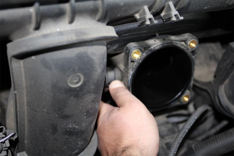
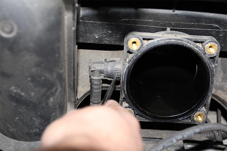
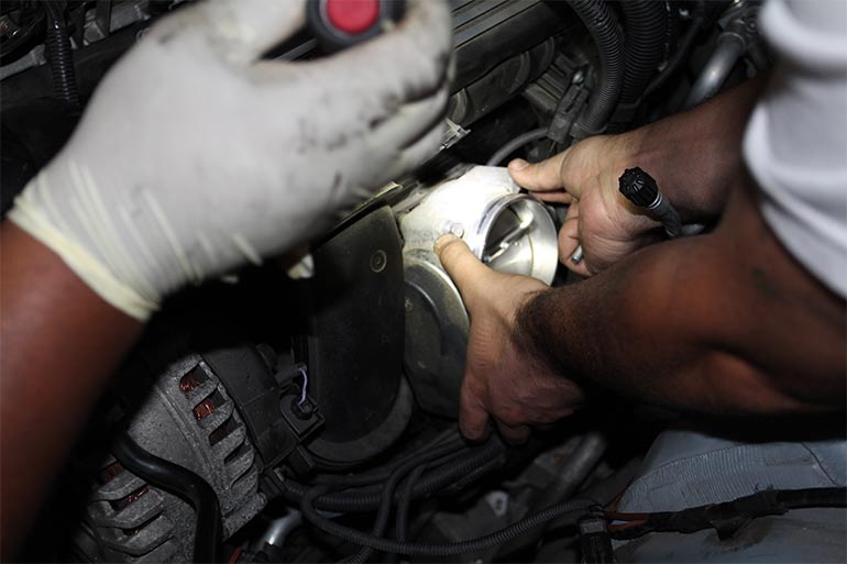
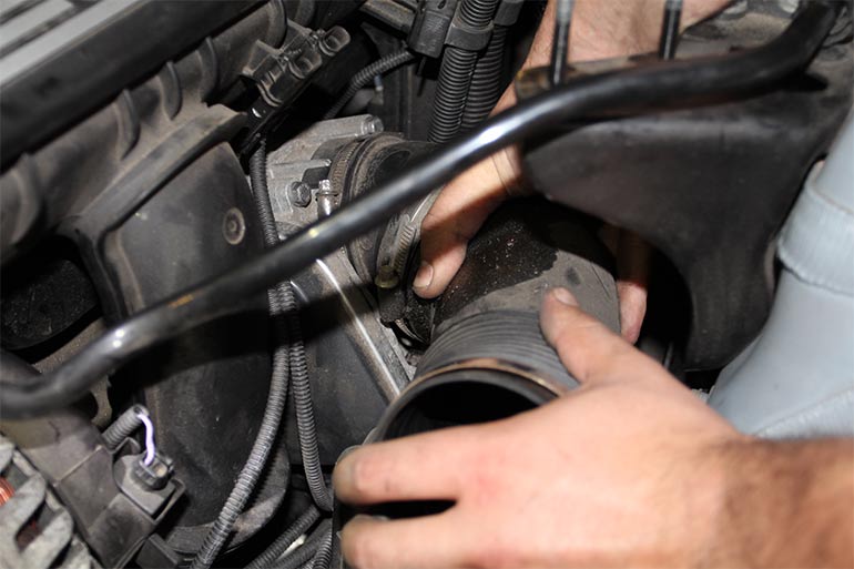
From here I got a better grip of a hose leading to the side of the throttle body mounting location and I removed it by pressing the two tabs on either side.
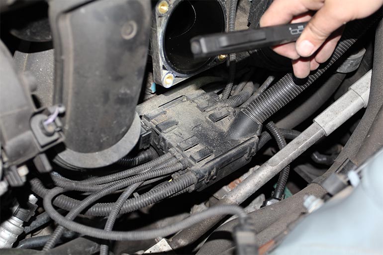
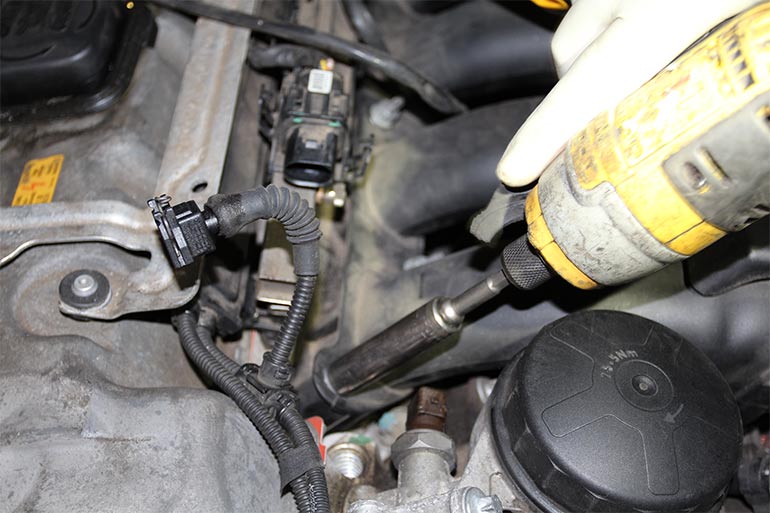
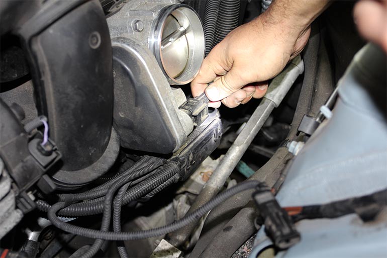
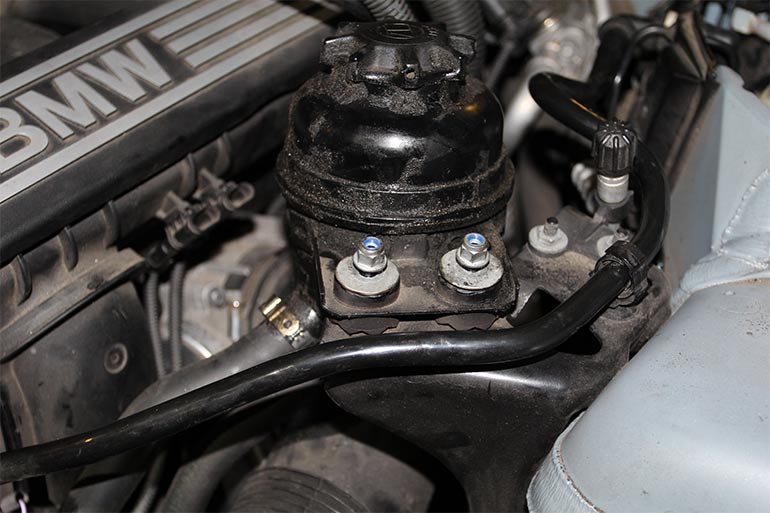
Back to the Junction box, now you get a clear view on the metal tabs you needed to work at and unhook, yea, good luck with that BMW. I simply unbolted the junction box bracket from the intake manifold by way of the two T27 torx socket and rested the box down and out of the way.
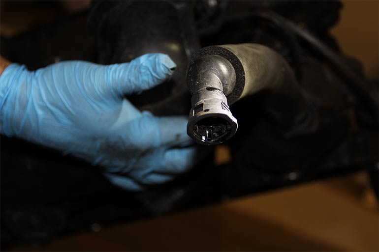
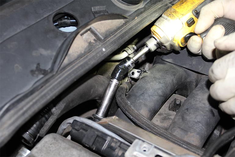
Then we began removing the 7 intake manifold bolts and nuts from the cylinder head. And removed the fuel line at the rail, setting it aside with a latex glove over its mouth to prevent drips of gasoline.
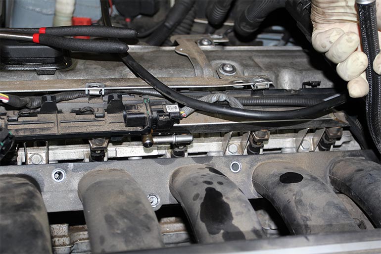
Then we two other electrical connectors towards the front of the engine near the rail that would get in the way of removing the intake manifold.
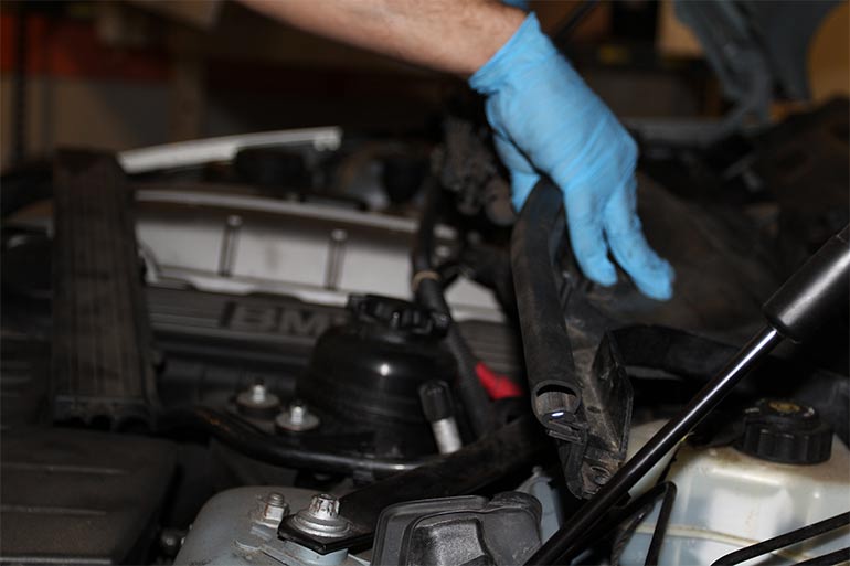
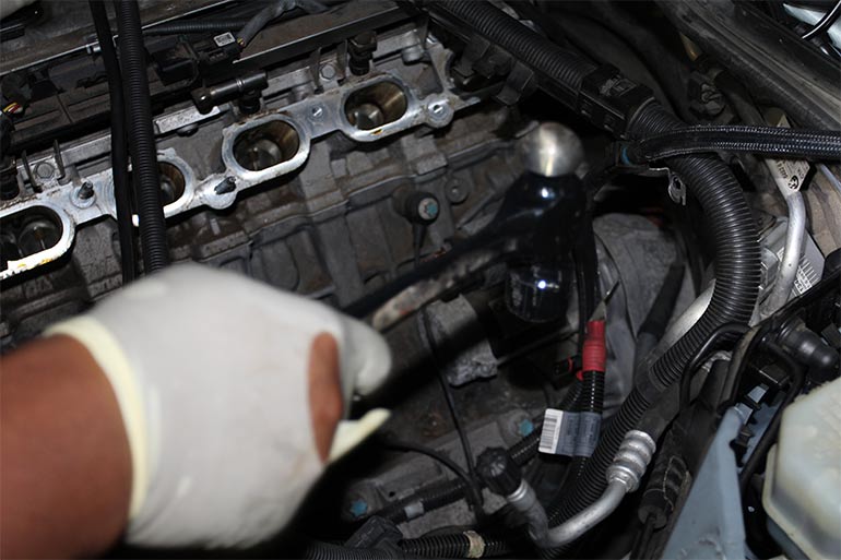
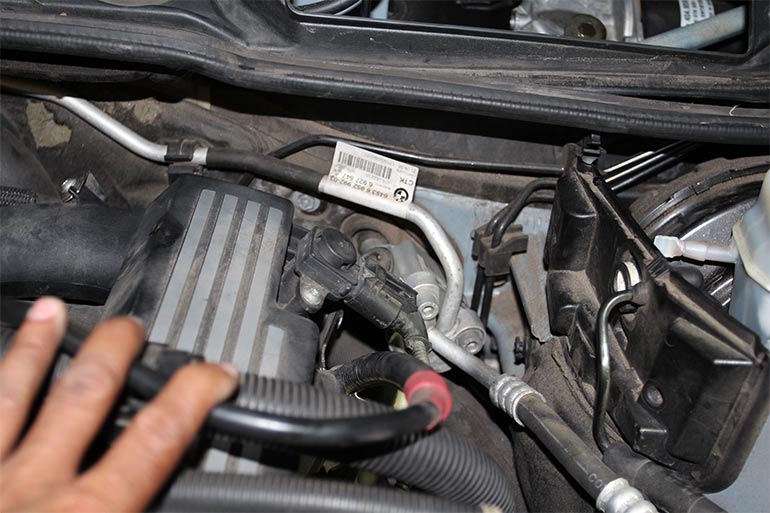
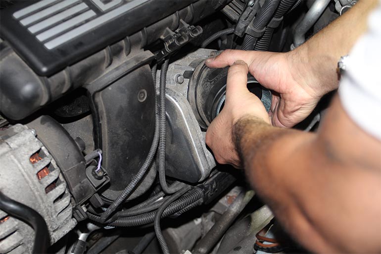
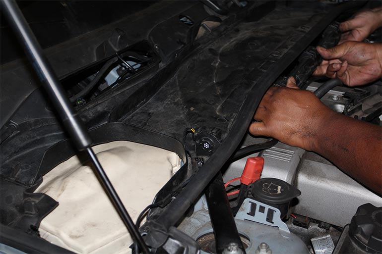
Now we can begin to lift on the intake manifold and separate it from the engine, there will be several small electrical connectors near the rear of the manifold that need to be disconnected on the way out (the only time you can get to them really) so be sure to move carefully and slowly. An extra set of hands here is helpful.
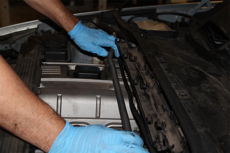
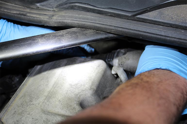
Before you can lift the manifold clear out of the way, you will need to deal with this oil return hose from your separator where it leads back down towards your pan. Remember to be careful and move slowly here as this hose is easy to break if you are pulling away to harshly. A long set of needle nose pliers here works well for the job.
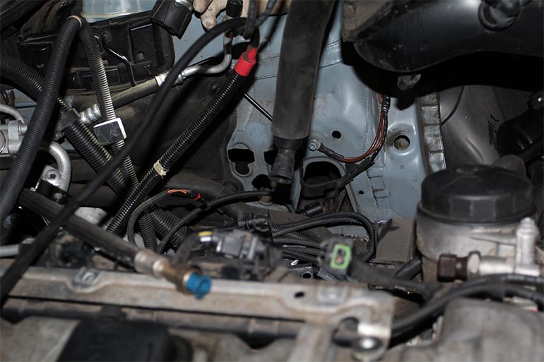
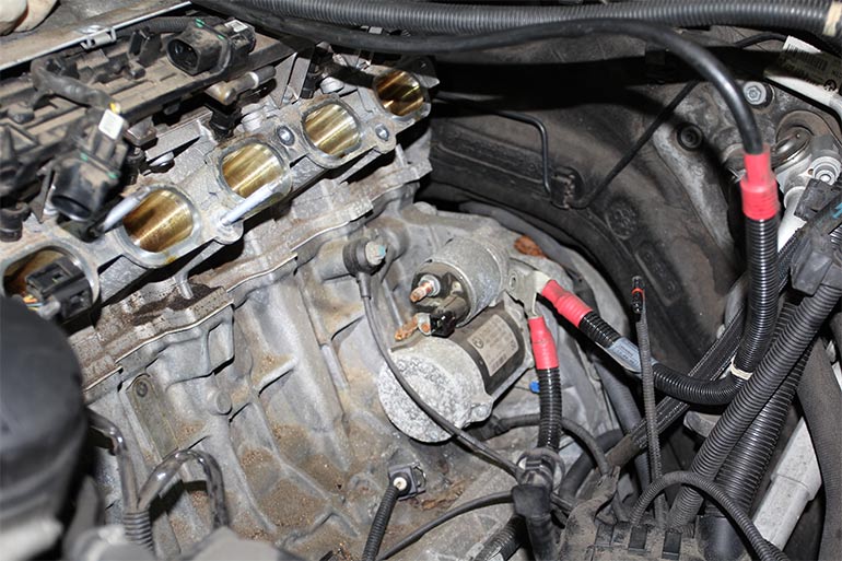
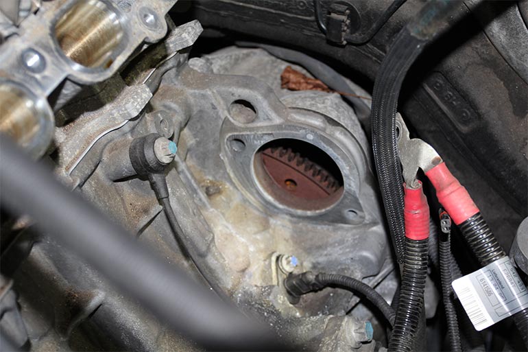
Before the manifold is completely removed you will need to disconnect the battery cable to the starter as now it should be fully visible. A 13mm socket on an extension will be needed.
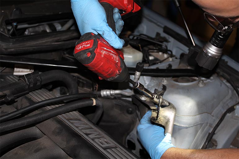
Now using a 11mm wrench and a steady hand you can begin to start removing the old starter bolts starting from the transmission bolt that goes in towards the motor on the top first. Then the lower bolt at the bottom with the same 11mm.
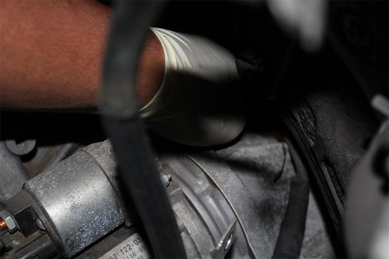
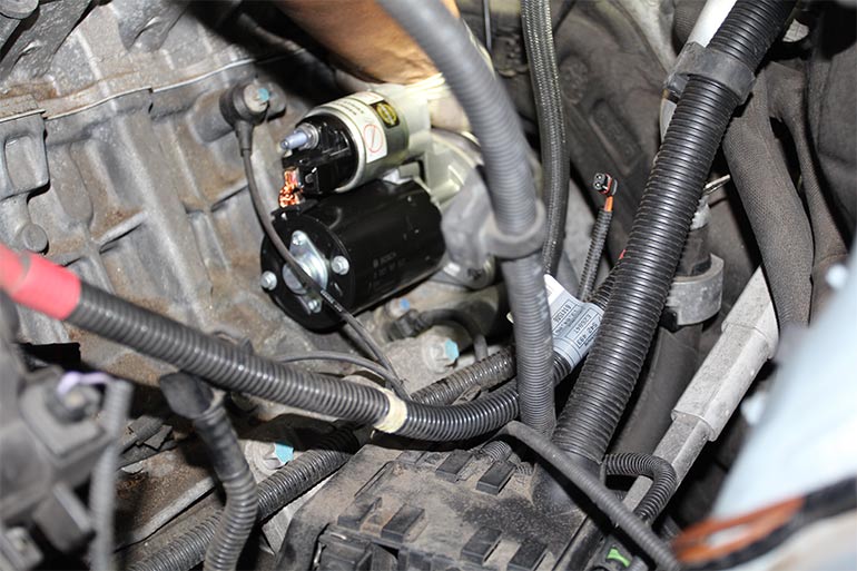
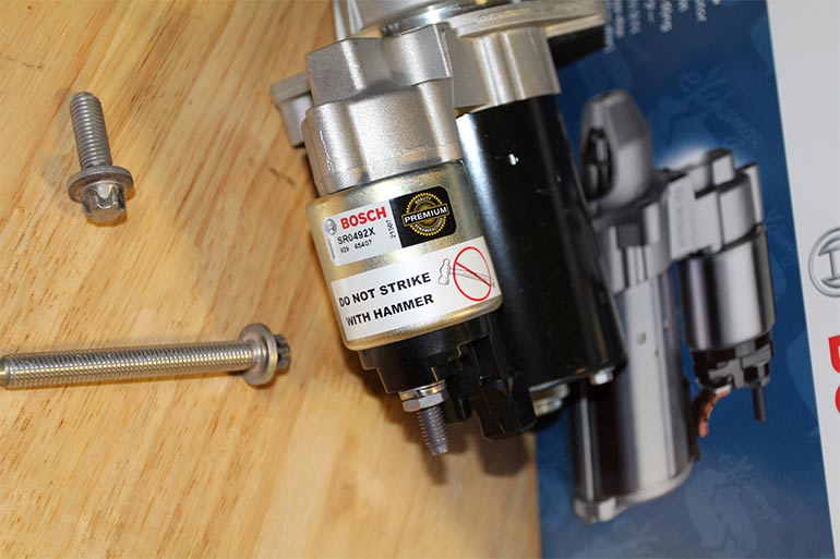
A couple of love taps with a BFH, will get your old starter out of the way.
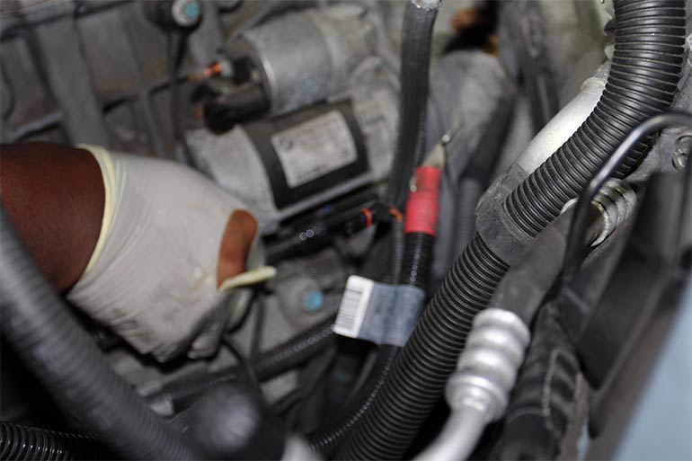
After that we can go ahead and install our replacement Bosch Starter, which coincidentally says do not strike with hammer on it, it's okay we only did that to the old one.
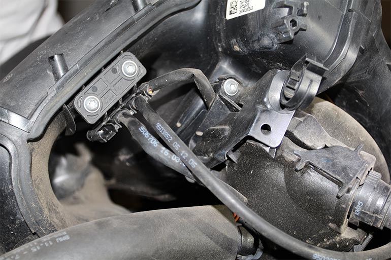
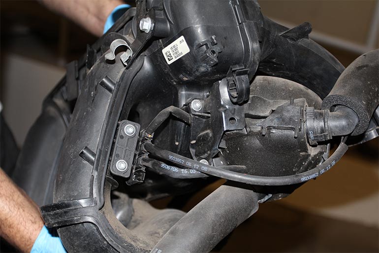
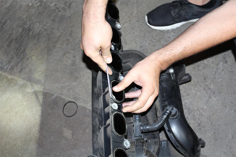
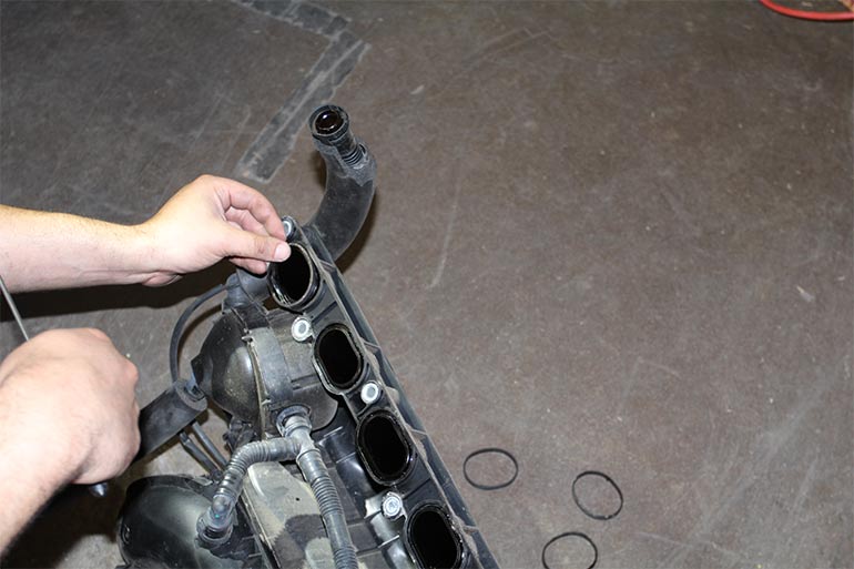
Working on the manifold I began removing and replacing the intake manifold gaskets using a new set from Victor Reinz.
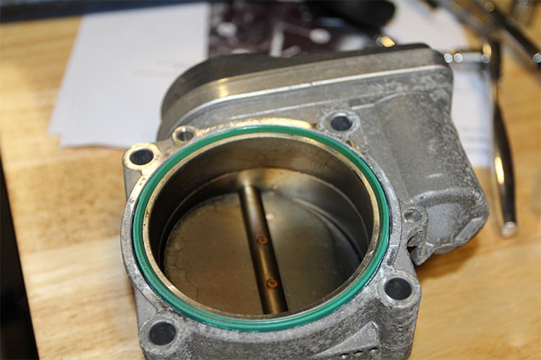
Since we removed the throttle body, we removed the old gasket and replaced it with a suitable unit from Victor Reinz as well.
We moved the intake manifold back into position and remembered to reinstall the lower breather hose we mentioned earlier when we had the chance. Also just before we placed the manifold on the head, we reattached the cable leading to the starter (Not visible)
Then we began tightening the manifold down to the head, using the same bolts we removed.
From here began the reassembly process, we fastened the harness connectors the corresponding bracket, fuel line and screw for mounting flange, and throttle body to intake.
We began then to reattach our electrical connectors at the throttle body and manifold.
Then our hose elbow at throttle body, along with our bracket for the power steering reservoir.
Then we move in and attached our vacuum hose by snapping it into our clip connector. Then installed our intake hose to elbow.
Repositioned out power steering reservoir and tightened the two 10mm nuts.
Then we brought in our air intake box. Pushed it into position and tightened our 10mm bolts and set in our air duct. Then bolted it down with the 2 T20 torx screws.
Back at the cowl we repositioned and tightened down our e-torx bolts.
Set in our cabin filter tray.
And laid in our harness cables in the corresponding slots.
Then we bolted down our cabin filter housing and side covers.
For the last step we went out back and reconnected and tightened down our battery cable firmly. From here we got inside the vehicle and turned her over. SHE LIVES!
All in all a moderate job to handle on your own and something you can feel confident to tackle if you are at all mechanically inclined. I would recommend having a hand with helping to carefully remove the intake manifold while disconnecting any lines and or electrical connectors you come across.
Now these engines will vary from model to model/year to year, so your setup may be a bit different than those depicted in this article, this guide should still apply and do not be alarmed if you notice yours is slightly different.
If you have any questions about this article or need any help please feel free to reach out to us at products@fcpeuro.com.