Normally this job would require the use of a special (Klann type) spring compressor, as access to the spring is limited by the design of the upper spring perch. The perch is attached to the car and not the shock. This is not a coil over design and the bracing of the spring perch prevents the use of ordinary compressors.
The “trick” is that by compressing the spring on the car, the nuts holding the shock can be removed and the spring unloaded completely while still on the car, without an external spring compressor. The catch is that you need to remove the half shafts and loosen the control arm bushings to allow that to happen.
This job is not wildly complicated, but requires doing most of a ball joint and all of the half shaft jobs before you can start on the shocks. I spent a week, mostly cogitating when I got stuck. Actual contact time was several hours, and the second shock took considerably less time.
The procedure is described for one side at a time, the exception being the sway bar, which needs to have the end clamps and rubber bushings off of both sides. Read the procedure, look at the pictures, re-read the procedure.
This the second time through for me, although last time I paid an indie mechanic based on the belief that the Klann type spring compressor was necessary. Now that I know different (and it’s warmer), I wasn’t about to pass a second time.
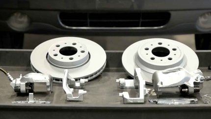
I bought the kit from FCP Euro: Bilstein shocks, new upper shock bushings, nuts and washer, and a new shock yoke nut and bolt. The old shocks were also Bilsteins.
Tools:
- In addition to standard sized sockets, you’ll need 18, 21, and 27 mm sockets and 18 and 21 mm combination open/closed-end wrenches. I have no idea why Mercedes likes off sizes. Maybe they’re English? These are pretty useful for Merc suspension.
- Rubber mallet to tap the half shafts back into position on reassembly.
- A BIG ball joint press. I never had any luck with other tools. Wind it up and whack it: BANG!
- Torque wrench. Mine maxes out at less than the 199 ft-lbs for the axle bolts so be aware.
- A home-made slide hammer and clamp. Supposedly, an actual Mercedes passenger side half shaft has a slot that allows you to pry it out. My aftermarket half shaft was featureless. I fabricated this from a 3 foot x 1 x 1/16 inch aluminum strip from Lowes. It took 30 minutes to make and worked the first time.
Prep:
- Loosen axle bolts with car on the ground, or get someone to push on the brakes. I didn’t want to put a screwdriver into my nice new rotors.
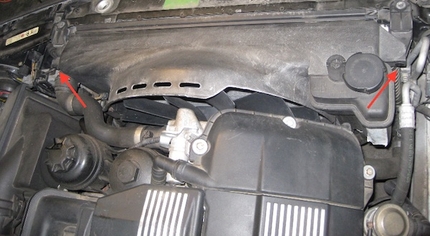
- Remove front drip pan (4 bolts, 2 clips). You need this off to loosen the control arm bushings.
- Jack car up on both sides (front) to unload sway bar. Use jack stands.
- Remove front wheel.
- Remove sway bar clips and rubber bushing.
- Loosen bolts holding control arm bushings, 2 per side. You really do need to do this as there isn’t nearly enough give in the bushings to allow the spring to unload completely. Don’t skip this.
- Remove nut from ball joint at bottom of hub.
- Press out ball joint from hub. This was when I noticed the rotted boot on one of the ball joints. More joy.
- Pull the hub off of the half shaft and use wire or tie downs to hold it away from the control arm. On the driver’s side there’s a convenient exposed brace at the back of the fender well. On the passenger side I left the jack engaged (in addition to the jack stand) and used the jack.
Get started:
- Remove headlight position sensor on front of passenger control arm.
- Remove brake line bracket from rear of shock yoke (2 x M6 socket head).
- Remove nut on shock yoke bushing.
- The control arm will drop completely loose, and land on the sway bar. To get the sway bar on top of the mounting tab, use the closed end of a combination wrench on the sway bar and lever the bar around the tab so that its now above the tab. This will allow the control arm to pivot to the ground.
- NOTE: you really do need to have both sides of the sway bar free, otherwise it’ll hang up on the control arm yoke and prevent the control arm from getting out of the way sufficiently to remove the half shaft.
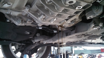
Remove half shaft. On the passenger side, there was no way to pull/yank on the half shaft. The spline in the engine has a spring clip, but the spline in the CV didn’t, so pulling just disengaged the spline from the CV and started stretching the rubber boot. I fabricated a clamp and slide hammer from a 1 x 1/16” x 3 foot aluminum strip from Lowes. The clamp is 11.25” long and the tabs are added to that length and folded over, as shown. The bolt is 1⁄4-20 and the steel rectangles are from a kitchen cabinet, so I assume they're home depot type parts. The socket is a 1” drive. Any size will do. The idea is to yank the half shaft out by the “can”. The hammer part was a big socket. Clamp the slide to the “can” and use the hammer to pop out the half shaft. On the driver’s side, it is captured, so it can be popped out without tools.
Now for the fun part:
- Once the half shaft is out, put the control arm back into the shock yoke and replace the bolt in the shock yoke and control arm. This is going to be your spring compressor.
- Remove the dust cover from the shock top and remove ONE of the pair of nuts. You can loosen the second nut until the top of the nut is even with the end of the threads.
- Place the jack under the bushing at the shock yoke and jack up the spring. I didn’t use the ball joint because I was worried about bending the alignment pin. You’ll know its compressed enough when the remaining nut on the shock top is raised up slightly from the metal washer. The nut should come off easily.
- Carefully, slowly, lower the control arm. It’s gonna drop quite a lot before the spring is loose. If you have a small 1 1⁄2 ton jack you may need to use some wooden blocks so you have enough total throw. I used a larger jack on the driver’s side.
- With the jack out of the way, the shock yoke bolt should come out by hand, and make sure you’re holding the shock/spring assembly as it will fall out once the bolt is removed. The spring has a small end (the bottom), so you’ll have to take of the shock dust cover to get the spring off.
- NOTE: There has been a lot of discussion about replacing the springs. For whatever reason, they seem to fail a lot. Maybe rocks get caught between the coils. I replaced the springs last time, so I’m keeping them this time.
- Remove the old rubber bushing and washer from the top of the shock mount hole.
- NOTE: there is a rubber ring that sits on top of the spring. It stayed up inside the spring perch and leapt to safety when I wasn’t looking. By the time I saw it, I had the new shock and half shaft reinstalled. I had to repeat the whole procedure. Don’t lose sight of the top rubber spring seat. The bottom seat is attached to the shock (at least it was on the Bilsteins).
- Wrestle the new shock/spring into place (top end first) and get the shock yoke bolt into place.
- When reinstalling the shock, you’ll have to push on the shock top to get it aligned with the hole. There is a metal sleeve on the shock shaft that you can slide up and cover the threads. It’ll stay up because the rubber bushing will hold it. Don’t forget the spring top rubber and metal washer.
- With the shock jacked up into the hole, place the second rubber bushing and metal washer over the shock shaft and thread the first nut on. I tightened the nut as much as I could and put the second nut on. As others have noted, you won’t see as many threads exposed as you had before. To compress the rubber further you would need a “go-thru” socket and a tool to hold the shock shaft. You can decide later if you want to retighten them.
- Replace the dust cover.
- With shock top attached, lower the control arm, use the box wrench trick to lever the sway bar around the tab, lower the control the rest of the way and remove the shock yoke bolt.
- Reinstall the half shaft. Once the splines are lined up, pound them in with a rubber mallet.
- Raise the control arm and lever the sway bar back underneath the tab, reinstall the shock yoke bolt and hand tighten.
- I was surprised to find the “rest” position of the control arm was with the suspension unloaded. That means that with the car on the ground, the control arm bushings are already loaded. On other cars, the bushings are tightened with the car on the ground, or the suspension loaded. I loaded the suspension some before tightening the bushings for the shock yoke and control arm.
- Reattach the brake hose clamp.
- Reattach the headlight aiming link (passenger side)
- Reattach the sway bar clamps.
- Reattach ball joint.
- Reinstall the engine cover.
- Put the wheels back on.
- Re-torque axle nuts.
Pictures
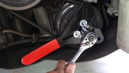
Ball joint press on the bottom ball joint: Remove the nut, apply the press, wind it up and smack it with a metal tool. I also use some liquid wrench on the threads.
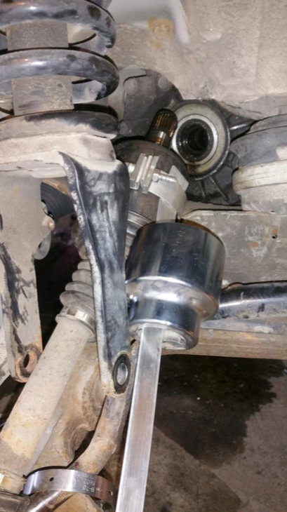
Slide hammer and clamp in place on the half shaft. The clamp is 11.25” long and the tabs are added to that length and folded over, as shown. The bolt is 1⁄4-20 and the steel rectangles are from a kitchen cabinet, so I assume they're home depot type parts. The socket is a 1” drive. Any size will do. The idea is to yank the half shaft out by the “can”.
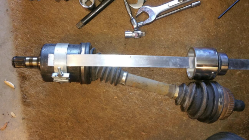
Another picture of the half shaft and clamp/slide puller. The slide is held in place by the clamp because the aluminum strip has been folded over. Same at the far end with a hole drilled and a bolt in place for the socket to impact.
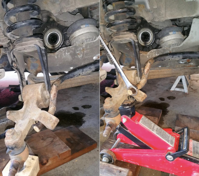
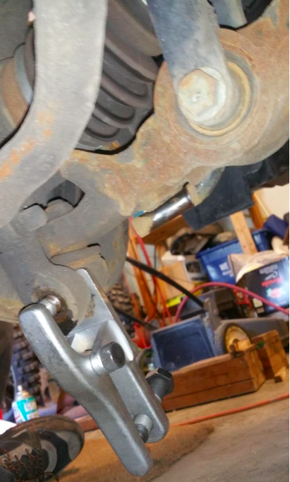
(left) With the half shaft removed, reinsert the bolt through the yoke. (right) Ready to lower the shock. Note that the box wrench has been used to lever the sway bar end around the mounting tab. This will allow the control arm to drop down low enough to unload the spring. Also note that on the left, for the half shaft, with the yoke attached, I’m able to raise the control arm from the ball joint. On the right, I’m lifting using the control arm bushing. I had to put the small jack on wooden blocks to get enough throw. Once the shock nuts are off, the control arm drops down to the floor and using the ball joint as the lift point won’t allow enough travel to unload the spring.
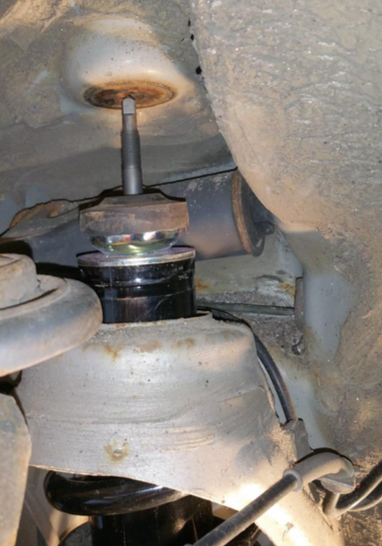
Shock lowered. When installing the new shock, you can use the metal collar (not shown) to protect the threads.
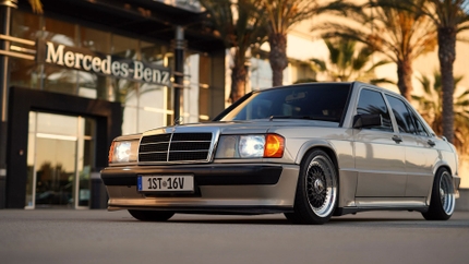
Shop BIlstein Front Suspension Kit